General Cranes Specifications
TECHNICAL SPECIFICATION OF "SUREKA" ELECTRICALLY OPERATED OVERHEAD TRAVELLING CRANE.
1. GENERAL
| Design: | The Crane is designed in accordance with IS: 807- 1976 code of practice for Design, Manufacture, Erection & Testing (structural portion of Cranes & Hoists) and IS: 3177-1999 Code of Practice for Design of Overhead Travelling Cranes. In the design of components adequate factor of safety as per relevant codes, shall be allowed. Impact, Fatigue, Wear & Stress concentration factors shall be taken into account wherever applicable. All drives will be designed with adequate margin to give high performance and efficiency. Safety arrangements shall be incorporated to prevent damage to the motors. |
|
| Steel: | Steel conforming to IS: 2062 or equivalent will be used in the manufacture of the main load bearing members of the crane structure. | |
| Materials & Workmanship: | All materials used in the manufacture of the crane will be selected from the best available quality for the purpose considering strength, durability and best engineering practice. Liberal factors of safety will be used through out the design, especially in the design of all those parts subjected to alternating stresses and shocks. Manufacturing of the equipment will be as per accepted and approved Engineering Practice. |
|
| Motors: | All motors will be crane duty, totally enclosed fan cooled A.C. induction type 6/8 poles and have reputed make such as B B / ALSTOM / CROMPTON / KEC. The motor horsepower, rating and type will be as mentioned in the main data. The mentioned motor horsepowers are tentative and may be changed suitably according to final design calculations. | |
| Gear Box: | All gearboxes used on the crane will be totally enclosed and dust proof construction. The gears will be helical / spur type and will run in an oil bath and hence no external lubrication will be required. Pinions will be of high carbon steel and gears will be cast / forged steel and will be keyed to the carbon steel shafts. Hobbling process will generate gears and pinions. The shafts rotates in anti friction type ball / roller bearings. Use of totally enclosed gearboxes, though costlier, is desirable in view of the increased transmission efficiency and longer gear and bearing life. | |
| Brakes: | All the motions i.e. hoisting, cross traverse and Long travel will be provided with double shoe type, spring operated Electro Hydraulic Thruster released brakes. These brakes are of " Fail Safe " type. The brakes are automatically released when the motor circuit is "ON" and are applied when the motor circuit is "OFF". This features works as a positive safety device as the brakes automatically come into operation when the power supply fails. The brake for hoisting allows to control with safety lowering of load up to test load and when current is cut off or fails, arrest and hold load up to test load at any position of lift. The brakes for cross traversing and long travelling motions bring the crab, crane and load to rest without shocks. |
|
| Bearings: | All moving parts of the crane will be supported on antifriction type ball /roller bearings. Bush bearings will used only in equalizing sheave as it practically remains in stationery condition. | |
| Painting: | The structural parts of the crane will be thoroughly cleaned and given one coat of red oxide primer before despatch. Exposed machinery parts such as wheels, bright bars, etc. will be coated with anti corrosive paint. | |
| Lubrication: | The crane will be provided with all necessary lubrication fittings. | |
| Limiting: | Limiting dimensions and sizes of components mentioned DIMENSION in the "Main Data" and / or "Schedule of Technical Particulars" are tentative only and are to be confirmed by us after preparing the final design drawings. Purchaser's specific requirements in this connection if any will also be considered as much as possible. | |
| Operation: | The crane will be either from floor or from cabin as mentioned in the "Main Data" and / or "Schedule of Technical Particulars" A. Cabin In case of cabin operated crane the cabin will be of open type, fixed at one end of the bridge near the end carriage. The cabin will be provided with necessary fittings such as fan, chair, light and gong bell. Necessary ladder will be provided for access to the cabin from bridge platform. Controller in the cabin will be mounted in such a way that they can be easily operated while giving the operator full view of the load. The protective panel will be housed in the cabin so as to attend to all emergencies promptly. B. Pendant Push Button Station In case of floor operated crane, the pendant push button station will be suspended from one end of the bridge at a suitable height from the floor level. |
|
| Power: | Crane will be suitable for operation on 400/440 Volts, 3 phase, 50 cycles, A.C. Supply. Control Voltage will be 110 Volts A.C. through a control transformer. | |
2. TROLLEY
A. Crab Frame
The Crab frame work will be of all welded construction, fabricated from rolled steel sections and plates. The hoist and cross traverse machineries will be mounted on this frame.
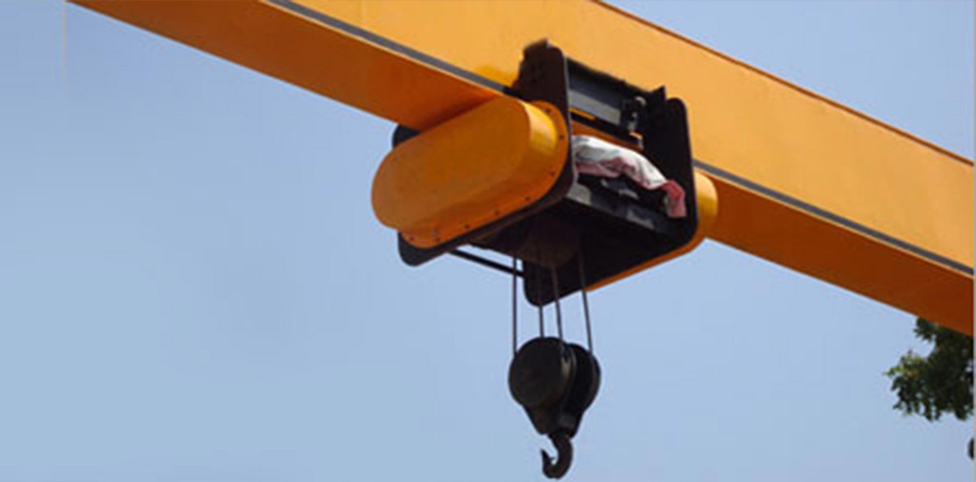
B. Hoist Mechanism
Hoist Mechanism consists of a motor, brake, shaft, couplings, totally enclosed oil splash lubricated dust proof construction gear box, rope drum, wire rope, sheaves, bottom block and limit switch.
Brake
Electro Hydraulic Thruster Brake will be provided between the Motor & Gear Box for the hoisting motion.
| Rope Drum: | The Rope Drum will be low carbon steel to IS:2062 fabricated instruction (duly stress relieved) having right & left hand spiral grooves machined to suit the hoisting ropes. The drum will be of such size that there will not be more than one layer of rope on the drum when the hook is at its highest position. Also the length of the drum will be such that, each load of rope has minimum 2 full turns on the drum when the hook is at it's lowest position and one spare groove for each rope lead when the hook is at it's highest position. Minimum diameter of rope drum measured at the bottom of the groove shall be 17 times the diameter of wire rope in case of class I & II duty cranes and 22 times the diameter of wire rope in case of class III & IV duty cranes. |
|
| Wire Rope: | Wire rope will be of best plough steel, fiber core, 6x37 OR 6 x 36 construction having tensile strength of 160 or 180 kgs/mm2. The wire rope will be confirm to IS-2266/1977 and have a minimum factor of safety 5 for class I duty cranes and 6 for class II, III, & IV duty cranes. | |
| Bottom Block: | The hook will be of single plain shank type conforming (Snatch Block) to B.S. 482 or equivalent, freely swiveling, and supported on a thrust bearing. | |
| Sheaves: | Machine grooved sheaves of preferred number diameters and materials MS/CS will be mounted on anti-friction type ball/roller bearings. adequate guards will be provided to prevent the rope from leaving the grooves of pulleys. The diameter of main sheaves at the bottom of grooves shall be minimum 17 times the diameter of wire rope in case of class I & II duty cranes and 22 times the diameter of wire rope in case of class III & IV duty cranes. The diameter at the bottom of the groove of equalizing sheave shall be selected from the values relating to main sheaves diameter shown in IS:3177-1977. |
|
| Limit Switch: | One number rotary type shunt connected limit switch of reputed make will be provided to prevent the over- lowering and over-hoisting motions. C. Auxilary Hoists If Auxiliary hoist is also provided its arrangement will be similar to the main hoist. D. Cross Traverse Mechinery Cross Traverse Machinery will consist of a motor, brake, shaft, couplings, limit switch and a totally enclosed oil splash lubricated dust proof construction gear box. |
|
| Wheels: | The output shaft of the gear box is extended on both sides and is coupled to the cross traverse bright bar shafting , which drives one wheel on each side. These wheels are of Cast/ Forged Steel double flanged direct drive type and are supported on 'L' type bearing housing. The 'L' type bearing housing have definite advantages, explained here below under the heading 'L' type bearing housings. | |
| 'L' Type Bearing Housing: | 1. They provide two load bearing surfaces at right angles to each other as against simple plumber blocks for bearings , which provide single bearing surface only. 2. Wheel load due to skewing of the crab being transferred to the structure through the machined grooves on the bearing housing and machined pad welded to the structure. Nounwanted stress due to bending and shear develops on the holding bolts (failure of which cause serious accidents in other type construction). 3.Ease of maintenance. The complete wheel assembly can be changed in matter of minutes, which otherwise can hold up the crane in a brake-down condition indefinitely. |
|
| Prevention Of Misalignment: | The Cross Traverse wheels will be keyed to the axles supported on ball/rollers bearings, which not only withstand more axle thrust but also allow the axle to take bending deflection and linear expansion due to temperature rise. | |
| Brake: | One number Electro Hydraulic Thruster Brake will be provided for the cross traverse motion. | |
| Geared: | Flexible Geared Couplings will be provided between COUPLINGS output shaft of the gear box and wheel axles on "Floating Shaft" principle. This transmission system has the followings advantages. 1. Simple in design & composed of few parts. 2. No springs to crystallize or break. 3. No rubber bushes, which require frequent replacement. 4. It is self aligning with no binding action at any point of its revolution. 5. Crowned tooth are free to align themselves as in a ball and socket joint. 6. Can be used on reversing service without any noise or vibration. 7. Exceptionally long life. 8. Accurately machined for ultimate performance. 9. Simple to align, install and easy to maintain. 10. In capacity to transmit torque, it is the smallest in size and weight in comparison with any other type of flexible coupling. This type of arrangement of providing geared couplings (known as Floating Shaft" arrangement) has the following advantages : 1. Prevention of misalignment of the line shaft. 2. Prevention of misalignment arising out of differential deflection of crane girder and shaft. 3. Prevention of development of any undue strain in the platform supports which otherwise may give way due to excessive alternate stresses developed in line shaft with rigid couplings. Flexible couplings of Pin Bush type will be provided between cross traverse motor and gearbox. |
|
| Geared: | Flexible Geared Couplings will be provided between COUPLINGS output shaft of the gear box and wheel axles on "Floating Shaft" principle. This transmission system has the followings advantages. | |
| Limit Switch: | One number two ways lower type shunt connected limit switch will be provided to prevent over-traversing on either side of bridge. | |
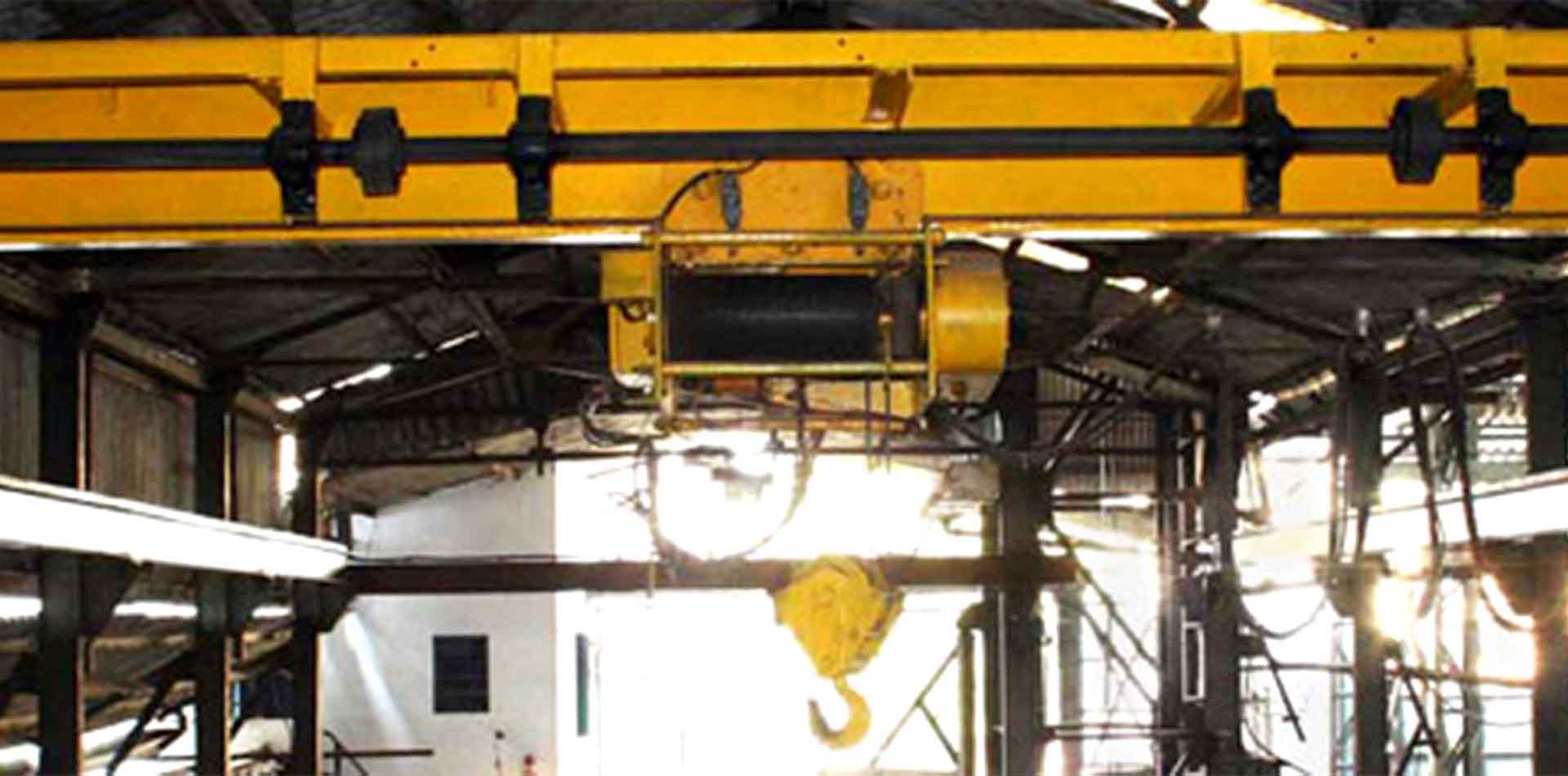
3. BRIDGE
The Girders will be of plate welded box type construction designed to sustain all the stresses arising due to vertical and lateral forces with impact to which they are subjected. The maximum vertical deflection of the main girder due to live load with the trolley position at the center of the span will be limited to l/900 of the span.
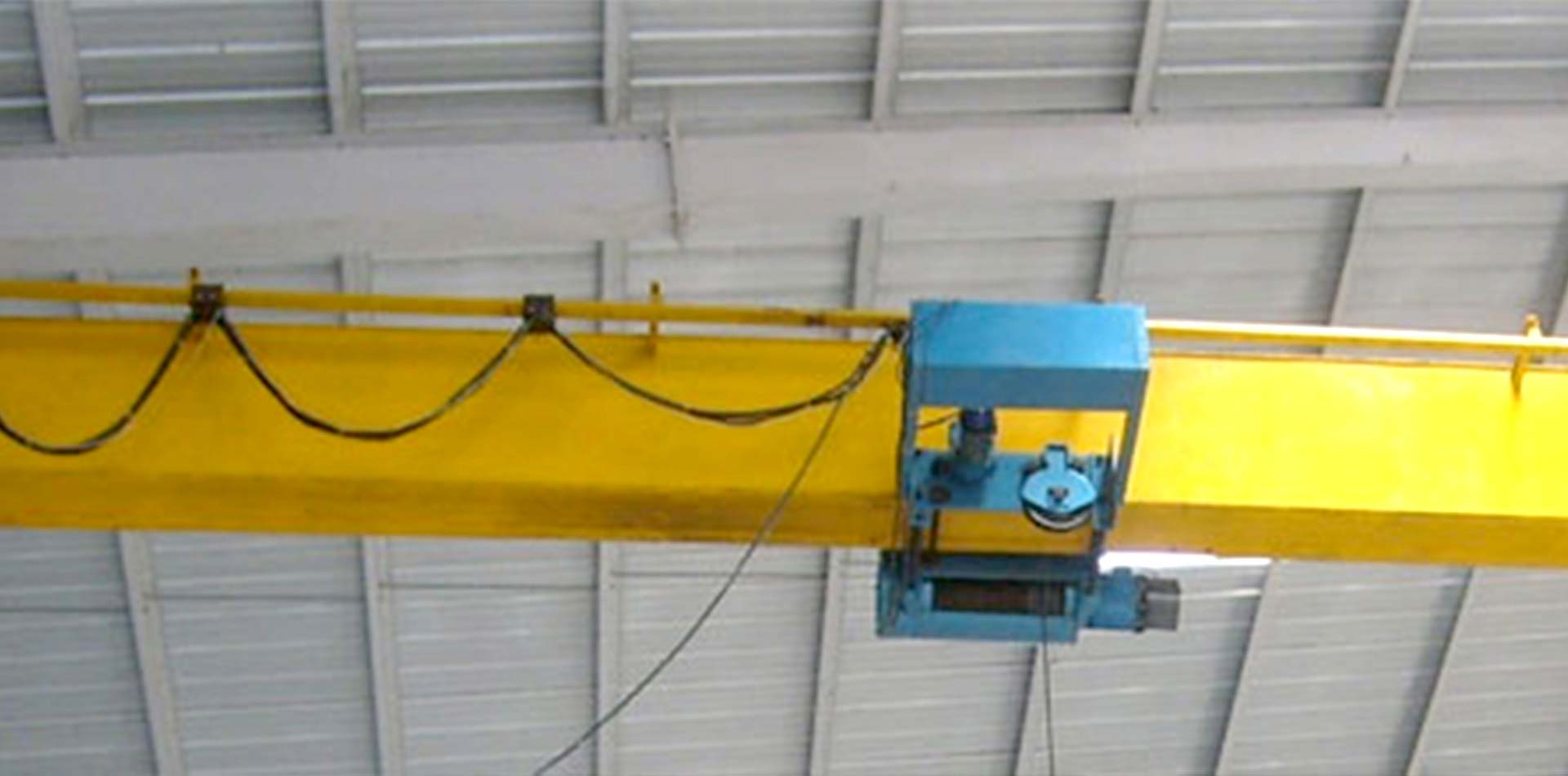
| Cross Bars: | Power supply to the trolley will be fed through festoon type flexible trailing PVC cables. These cables will be mounted either on trailing trolleys moving on a separate I-sectionsteel track or on curtain rings moving on a steel wire. | |
| Trolley Track: | WSuitable square section steel track/ rail section will be provided for traverse of the trolley. This will be welded on to the girder. | |
| End Stoppers: | Steel End Stoppers will be provided on either side of the bridge to limit the motion of the trolley. | |
| Platform: | A non-skid steel platform with suitable hand railing will be provided on the driving side throughout the crane span to facilitate maintenance. Two short platforms at either end will be provided on the idle side for maintenance of idler wheel assembles. | |
4. END CARRIAGES
End carriages will be fabricated from rolled steel sections and plates with adequate diaphragms and stiffeners in the form of rigid box construction. The girders with gusset plates will be set on to the end carriages and fastened with machined bolts in reamed holes. Rubber buffers will be provided on either side of the end carriages.
5. LONG TRAVEL MACHINERY
Depending upon the span of the crane, the driving machinery for the Long Travel motion will be either single motor drive or twin motor drive as indicated by the quantity of LT motors mentioned in the 'Main Data' and or "Schedule of Technical Particulars.
| Twin Motor Drive Arrange: | In this case instead of one, two independent driving units (comprising of a motor, a gear box and a brake) are placed on each near the end carriages Each driving unit is mounted on a specially designed rigid frame mounted on the bridge girder and removable as a complete system. The Electrical control will be so designed that in the event of tripping of one motor, the power supply to the other motor will get instantaneously disconnected so as to bring the long travel motion to stop. |
|
| Wheels: | Track wheels will be of Cast/Forged steel, double flange type directly coupled to the long travel shafts. Hardness of the wheels will be 250 to 300 BHN. These wheels will be supported on `L' type bearing housings for easy remove from the point of view of maintenance. | |
| Couplings: | The entire transmission system on the output shaft of the long travel gear box will be designed to incorporate use of Flexible Geared Couplings on `Floating Shaft' principle. Flexible couplings of pin and bush type will be provided between the long travels gear box and the motor. | |
| Limit Switch: | One Number two way lever type shunt connected limit switch will be provided to prevent over travelling of the crane on either side. | |
| Main Current Collection System: | Four Numbers Gun Metal shoe type current collectors with renewable carbon inserts in case of bars copper wire type down shop leads and case iron gravity type current collectors in case of M.S. Angle type down shop leads will be mounted on one side of the crane bridge for power collection. | |
6. CONTROL & PROTECTIVE PANEL
| Resistance: | Resistances will be of stainless steel formed grid type housed in ventilated steel cabinet. | |
| Control: | Control of the crane will be from cabin through master controllers / drum controllers or from floor through pendant push button stations as specified in the main data. Resistances in the rotor circuit of Slipring induction motors will be cut off in steps through magnetic contacts and time lag relays to give smooth acceleration and deceleration to the crane, in case of master controller/push button operated crane. In case of master controller control, AC dynamic braking system will be provided for hoisting. Rated speeds for hoisting and lowering motion at full load will be achieved through master controller on various notches. 25% of rated speed at full load lowering will be achieved by single phasing counter torque method. | |
| Protective Panel: | A protective Panel of sheet metal construction will be provided which will house the following: 1. Isolating switch interlocked with panel door. 2. Push Button for stopping all the motions.This also acts as Emergency stop. 3. Triple pole thermal overload relays for individual motors. 4. One set of fuses for each motor. 5. One contactor type circuit breaker. 6. One transformer for low voltage supply. 7. One set of switch fuses for transformer protection. 8. One indicating lamp. |
|
| Control Panels: | Motor Control Panel(s) provided for motors will be of sheet metal construction and located firmly on the drive platform on stands. | |
| Test Cetificates: | Test Certificates for motors, wire ropes, and hooks of brakes will be obtained from the respective manufacturers and submitted along with the crane. | |
| Inspection & Testing: | The Crane will be assembled and tested at our works. Purchaser's Representative can be present for the above inspection, for which intimation will be given well in advance. | |
| Guarantee: | Our supplies are guaranteed for free replacement / repairs of parts ex - our works against faulty or defective materials & workmanship, provided the defects are not due to damage during transit, bad storage,and misused or mishandling of the equipment at customer's site or due to normal wear and tear. However, the defects found in any part should be reported to us immediately after observation and the same shall be returned to us without making any alteration freight paid, for our inspection. | |
| Name Plates: | Two Name Plates with our name and serial number the year of manufacture and safe working load of the crane will be supplied for affixing on each side of the bridge. The lettering on name plates will be visible from ground. | |